News
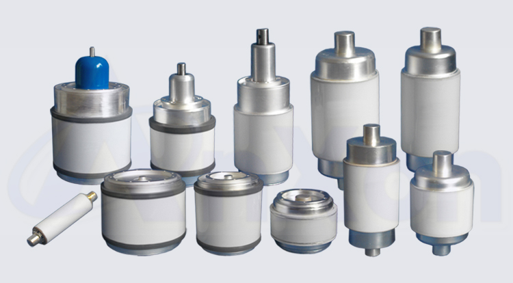
Vacuum Capacitor
Vacuum Capacitor Characteristics and Applications
Vacuum variable capacitor
A vacuum variable capacitor is a variable capacitor which uses a high vacuum as the dielectric instead of air or other insulating material. This allows for a higher voltage rating using a smaller total volume. There are several different designs in vacuum variables. The most common form is inter-meshed concentric cylinders, which are contained within a glass or ceramic vacuum envelope, similar to an electron tube. A metal bellows is used to maintain a vacuum seal while allowing positional control for the moving parts of the capacitor.
Invention
NikolaTesla filed a patent in 1896 for a vacuum capacitor. The original use was to enhance the quality of the electrical components for handling "currents of high frequency and potential". These components were necessary for the DC impulse research which Tesla was studying. Commercial products have been available since 1942.
Applications
Vacuum variable capacitors are commonly used in high-voltage applications: 5000 volts(5kV) and above. They are used in equipment such as high-powered broadcast transmitters, amateur radio RF amplifiers and large antenna tuners.Industrially they are used in plasma generating equipment, for dielectric heating, and in semiconductor manufacturing. The main applications today are RF plasmas of 2 to 160 MHz where the vacuum capacitor is used as the impedance variation part in an automatic matching network in the fabrication of chips and flat panel displays.
Fixed-value vacuum capacitor
Other variations of vacuum capacitors include fixed-value capacitors, which are designed very much like the variable versions with the exception of an adjustment mechanism.
Comparison
When compared to other variable capacitors, vacuum variables tend to be more precise and more stable. This is due to the vacuum itself. Because of the sealed chamber, the dielectric constant remains the same over a wider range of operating conditions. With air variable capacitors, the air moving around the plates may change the value slightly; often it is not much but in some applications it is enough to cause undesirable effects.
Vacuum variable capacitors are generally more expensive than air variable capacitors.This is primarily due to their design and the materials used. Although most use copper and glass, some may use other materials such as ceramics and metals such as gold and silver. Vacuum variables also vary in adjustment mechanisms.
Vacuum Capacitor Characteristics
The Tech Note has been developed to explain the primary characteristics that are considered when developing vacuum capacitors. Additionally this document will provide a clear description of terms used in the capacitor industry.
Current/Voltage
Maximum operating current for vacuum capacitors is limited by temperature rise and working voltage. At low capacitive reactance (high capacitance) values it may be impossible to apply rated voltage without exceeding rated current.Therefore, the vacuum capacitor will be current limited. At high capacitive reactance (low capacitance) values, it may be impossible to apply rated current without exceeding rated voltage and the capacitor will be voltage limited.These operational characteristics are indicated for each capacitor model.
Temperature
vacuum capacitors are designed to meet MIL-C-23183 specifications. Based upon actual current tests, most ceramic capacitors are rated for a maximum operating temperature of 120°C (250°F) and glass capacitors for 87°C (188°F)with normal convection cooling at an ambient temperature of 25°C (72°F).Derating curves for elevated ambient temperature operation are available upon request.
Fixed capacitors with a nominal capacitance above 50pF shall be within ±5%. Capacitors with a nominal capacitance of 50pF or less shall be within ±10%,or 0.5pF, whichever is greater. For variable capacitors, the low end will be equal to or less than minimum rating. The capacitance change is substantially uniform with rotation, and there are no capacitance reversals. Capacitance is within ±10% of the nominal value of the curves shown (Capacity vs. Turns), when the turns setting for reference purposes (defines point) is established near the low capacity end of the linear portion of this curve.
Automatic Shorting Feature
A number of variable capacitors have been designed with an internal shorting device that shorts out the capacitor when it has been turned beyond maximum rated capacitance. This feature is useful for tuning antenna couplers without the vacuum capacitor in the circuit and also serves as a reference point for adjusting the capacitor to a previously measured capacitance value.
Tracking
Variable Capacitors will track within 10% if set together near the low capacity end of the linear portion of the curve. On special order, units may be obtained to closer tracking tolerances.
Torque/Direct Pull
In variable capacitors, the linear sliding motion of the moving electrode assembly is converted to rotary tuning via a threaded shaft. The torque values given in the tables are the maximum torque needed to reach minimum capacitance when rotated with a standard lead screw; the torque required to tune away from minimum may be less than half this value.
For most variable capacitors, direct pull tuning is a possible alternative to rotary tuning. Maximum required pull force values are also given in the tables.
Capacitance range end-stops are built into every variable capacitor. It is recommended that the user install his own stops to prevent damage from gear-reduction drives.
In addition, also offers several" Adjustable" capacitors which are designed to be operated as a fixed capacitor, but can be hand adjusted to any value within their range and then locked in position with a locking nut.
Quality Factor (Q)
Extremely low losses occur in vacuum capacitors because of the vacuum dielectric,compact construction, and the use of low loss glass or ceramic envelopes as well as copper and precious metal solder construction. Consequently, vacuum capacitors are able to handle large RF currents at high RF frequencies that would destroy other types of capacitors. The "Q" factor, or ratio of stored energy to dissipated energy, is typically in the order of 1000 or 5000 or higher.
Because Q is a function of frequency, capacity and E.S.R. (Equivalent Series Resistance), it is perhaps more meaningful to consider the value of E.S.R. In modern high power capacitor applications, E.S.R. is significant for determining cooling requirements. The slight loss results from the RF resistance in the copper. Based upon actual tests, the E.S.R. value in not effected by change in capacity, other parameters being fixed. The value of E.S.R. varies over a range of 5 to 20 milliohms from 2.5 to 30MHz.
Thermal Stability
vacuum capacitors are designed to meet MIL-C-23183 specifications which state that the absolute value of the capacitance change with temperature shall not exceed 1.1% over the applicable operating temperature range. In typical tests,values for ceramic capacitors show stability within 50ppm/°C and for glass capacitors, 100ppm/°C. Specific tests can be performed upon individual capacitors on special request.
Salt Spray and Humidity
capacitors are designed to withstand the harmful effects of salt spray and humidity, without degradation in performance.
Inductance
The self-inductance of vacuum variable capacitors is typically in the order of 6 to 20nH while that of a fixed capacitor is significantly lower, in the range of 2 to 6nH.
For most applications, the self-inductance can be ignored. It becomes a factor only when the ratio of capacitive reactance to inductive reactance is small. Graphs of inductance or resonant frequency vs. capacity are available(see Figure 2).
Mechanical Life
The mechanical life of variable capacitors is related to length of stroke, speed of operation, bellows material, and total number of cycles. Extensive mechanical life tests have been run, operating units for complete cycles from maximum to minimum and back to maximum capacity covering 95% of the full stroke of the movable plates. Capacitors with a large bellows and a short stroke will have the greatest life expectancy under cycling operation. Our most recent models are rated for 1 million cycles, ideal for the semiconductor processing industry.
Application engineers can check your specific application to assure that the optimum capacitor is selected for your requirements.
【 Go Back 】 | 【 Print 】 | 【 Close this window 】